- One sided slotted waveguide antenna
- A standard 100x30x3mm aluminium profile was used as antenna body
The inner dimensions are:

- The critical wavelength for this waveguide with the H10 mde is
damit
 .
.
At the desired frequency
 the free space wavelength is calculated to:

Die
The waveguide wavelength is therefore :

- For N=12
milled slots on only one side, an antenna gain of approximatly

- can be expected. The vertical beam width
of the antenna is:

- The calculation of the mid offset after Sevenson calculates to:

- After solving the equation for x
x the mid offset is:

- The slot length for round slot ends calculated according to [1] is

- The Der Durchmesser des
Fräsers beträgt dabei 6mm.
- Der erste Schlitz wird
eine
 unterhalb der Kurzschlußebene angebracht, die weiteren
Schlitze folgen dann jeweils im
unterhalb der Kurzschlußebene angebracht, die weiteren
Schlitze folgen dann jeweils im
 -Abstand:
|
Schlitz-Nr |
Abstand |
|
1 |
- 44,1mm
|
|
2 |
- 132,3mm
|
|
3 |
- 220,6mm
|
|
4 |
- 308,8mm
|
|
5 |
- 397,1mm
|
|
6 |
- 485,3mm
|
|
7 |
- 573,5mm
|
|
8 |
- 661,8mm
|
|
9 |
- 750mm
|
|
10 |
- 838,3mm
|
|
11 |
- 926mm
|
|
12 |
- 1014,7mm
|

Abbildung
1: Position der Schlitze

Abbildung
2: Abmessungen eines Schlitzes
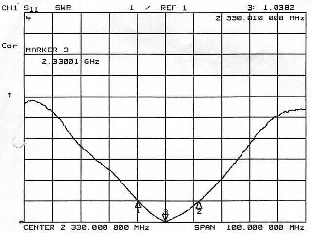
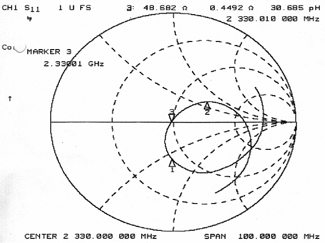
Messungen
Eingangsanpassung der
Antenne:
Betrag
Smith-Diagramm
Bild der fertigen Antenne
Antenne
Literatur
- [1] O. Nell, K.
Solbach, J. Dreier : Rundumstrahlende Hohlleiter-Schlitzantenne
für
Horizontalpolarisation
UKW-Berichte Heft 1/91, S.
50-55 und Heft 2/91, S. 71-77